Enterprise Network Design for Multi-Tenant Data Center 🖧 📐
Project Overview
This project involved the design and management of an enterprise network for a multi-tenant data center. The goal was to create a robust, scalable, and secure infrastructure to host services for multiple companies, ensuring high availability and disaster recovery capabilities.
The design encompasses both the physical and logical topologies of the data center, detailing the hardware, software, and configurations required to support the operational needs of five distinct companies with varying requirements for resource allocation, security, and disaster recovery.
🧠 What It Does
- Supports Multi-tenancy: Allocates dedicated and shared resources across five companies, ensuring logical segregation and security.
- Ensures High Availability: Implements redundancy at critical points, including server connections to multiple leaf switches, redundant links for border leaf switches and WAN routers, and dual ISP providers.
- Provides Disaster Recovery: Leverages AWS cloud environment for disaster recovery, using services like AWS CloudEndure for continuous replication of on-premise workloads to a staging VPC.
- Implements Microsegmentation: Achieves fine-grained security control using distributed firewalls and security groups.
- Manages Network Traffic: Utilizes proxy-based load balancers for distributing requests among web servers and distributed logical routers (DLRs) for routing traffic within and between tenants.
- Secures Connectivity: Enables secure remote and branch office access via IPsec VPN tunnels, with MPLS as the primary connectivity to the data center.
- Hosts Container Applications: For specific companies, containerized applications are deployed and managed using AWS EKS for scalability and fault tolerance.
🖧 Physical Topology
The physical design of the data center focuses on a spine-leaf architecture for high performance and scalability. Key components include Cisco Nexus spine switches and Cisco UCS leaf switches, connecting to Cisco UCS blade servers. Compute resources are organized into racks, with specific allocations for different companies and dedicated clusters for management and edge services. Redundancy is built in at multiple levels, from server NICs to ISP connections.
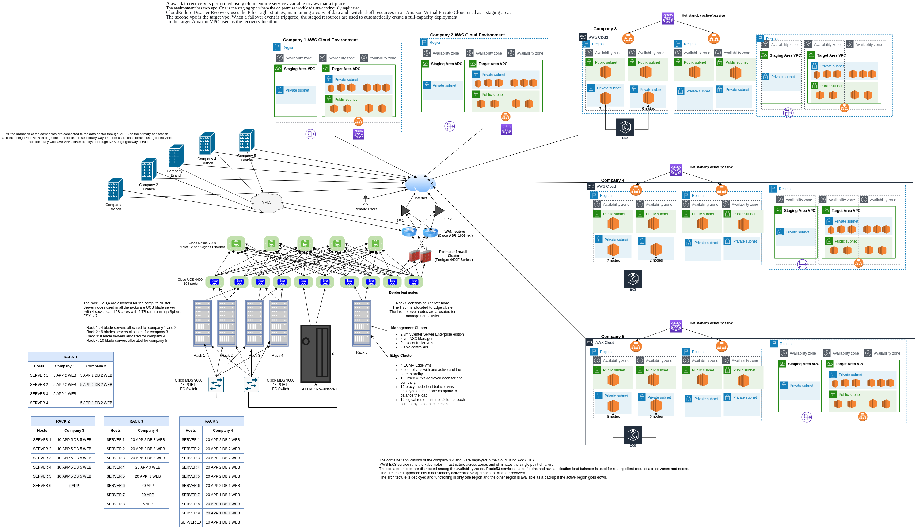
Physical network layout showing host connectivity, hypervisor placement, and NSX Edge/Controller appliance distribution.
🧠 Logical Topology
The logical topology leverages VMware NSX to achieve multi-tenancy and microsegmentation. Each company is provided with its own network services, including load balancers and distributed logical routers. Logical switches with unique VNIs segregate traffic, allowing for per-tier or per-tenant network designs. Secure access for remote users and branches is facilitated through NSX Edge services, deploying IPsec VPN instances per company.
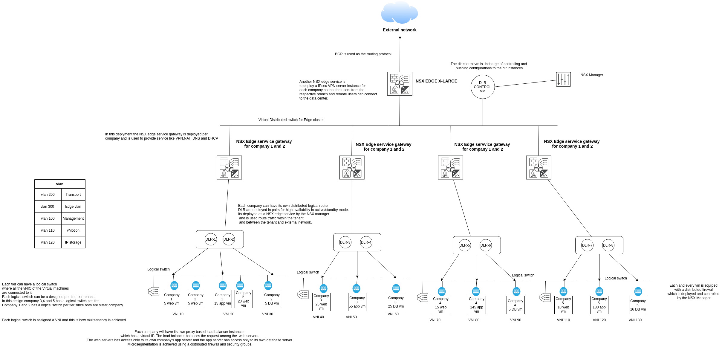
Logical network design illustrating tenant separation, NSX Edge services, DLRs, and logical switch assignments.
🧰 Technical Highlights
- Physical Infrastructure:
- Spine Switches: 5 x Cisco NEXUS 7000 (4-slot, 12-port Gigabit Ethernet).
- Leaf Switches: 10 x Cisco UCS 6400 (108 ports, 40GbE/10GbE).
- Server Nodes: Cisco UCS B480 M5 blade servers (4-socket, 28 cores, 6TB RAM).
- Compute Racks: 4 racks for compute clusters, with servers connected to two leaf nodes for redundancy.
- Management & Edge Racks: 1 rack with 8 blade servers running vSphere ESXi v7.0, allocated for Edge and Management clusters.
- Logical Design & Virtualization:
- Virtualization Platform: VMware vSphere ESXi v7.0.
- Network Virtualization: VMware NSX for managing NSX Manager, NSX Controllers, and NSX Edge gateway services (including DLRs, IPsec VPN, Load Balancers).
- Multi-tenancy: Achieved using VNIs for logical switches, allowing per-tier or per-tenant logical switch design.
- Microsegmentation: Implemented via distributed firewalls and security groups.
- Connectivity & Redundancy:
- Primary Connectivity: MPLS for branch connections to the data center.
- Secondary Connectivity: IPsec VPN over the internet.
- Internet Provision: Dual ISP providers.
- Cloud Integration (AWS):
- Disaster Recovery: AWS CloudEndure with a pilot light strategy, replicating workloads to a staging VPC and enabling failover to a target VPC.
- Container Orchestration: AWS EKS for deploying and managing container applications across availability zones.
- DNS & Load Balancing (Cloud): AWS Route53 and Application Load Balancer.
- Key Features:
- Logical segregation of tenant traffic and resources.
- High availability through redundant components and connections.
- Scalable design to accommodate future growth.
- Comprehensive disaster recovery strategy using public cloud integration.